Introduction
“What periodic structure is hidden in this signal?” “How much delay separates the outputs of two sensors?” The fundamental tool for answering these questions is the correlation function.
The Autocorrelation Function (ACF) measures the similarity between a signal and a time-shifted copy of itself, revealing periodic and repetitive structure. The Cross-Correlation Function (CCF), on the other hand, quantifies the similarity and time delay between two distinct signals. Both functions play a foundational role across signal processing, statistics, and machine learning.
This article provides a systematic treatment of autocorrelation and cross-correlation — from their mathematical definitions, through FFT-based fast computation, to practical applications in speech pitch estimation, delay estimation, and time-series analysis — all demonstrated in Python.
Definition and Properties of the Autocorrelation Function (ACF)
Continuous-Time Autocorrelation
For a finite-energy deterministic continuous-time signal \(x(t)\) , the autocorrelation function is defined as:
\[R_{xx}(\tau) = \int_{-\infty}^{\infty} x(t) \cdot x(t + \tau) \, dt \tag{1}\]For a stochastic process (random signal), it is defined via the expectation operator:
\[R_{xx}(\tau) = E[x(t) \cdot x(t + \tau)] \tag{2}\]Here \(\tau\) is the lag parameter.
Discrete-Time Autocorrelation
For a discrete-time signal \(x[n]\) of length \(N\) , the autocorrelation is defined as:
\[R_{xx}[l] = \sum_{n=-\infty}^{\infty} x[n] \cdot x[n + l] \tag{3}\]In practice, the normalized autocorrelation (scaled so that the maximum value equals 1) is often preferred, as it yields a similarity measure that is independent of the signal’s scale:
\[\rho_{xx}[l] = \frac{R_{xx}[l]}{R_{xx}[0]} \tag{4}\]Here \(R_{xx}[0] = \sum_n x[n]^2\) is the signal energy (or a quantity proportional to the variance), which is always positive.
Key Properties of the ACF
Even symmetry:
\[R_{xx}[-l] = R_{xx}[l] \tag{5}\]The value is unchanged when the sign of the lag is reversed.
Maximum at zero lag:
\[|R_{xx}[l]| \leq R_{xx}[0] \quad \text{for all } l \tag{6}\]After normalization this becomes \(|\rho_{xx}[l]| \leq 1\) .
Relationship to periodic signals: If \(x[n]\) has period \(T\) , then its ACF also has period \(T\) :
\[x[n + T] = x[n] \Rightarrow R_{xx}[l + T] = R_{xx}[l] \tag{7}\]Wiener–Khinchin theorem: The Fourier transform of the autocorrelation function equals the power spectral density (PSD):
\[S_{xx}(f) = \mathcal{F}\{R_{xx}[\tau]\}(f) \tag{8}\]This fundamental theorem shows that the ACF and the power spectrum are equivalent representations of the same information.
Definition of the Cross-Correlation Function (CCF)
The cross-correlation function between two signals \(x[n]\) and \(y[n]\) is defined as:
\[R_{xy}[l] = \sum_{n=-\infty}^{\infty} x[n] \cdot y[n + l] \tag{9}\]The lag \(l^*\) at which \(R_{xy}[l]\) is maximized indicates how many samples \(y\) leads (or lags) \(x\) :
\[l^* = \arg\max_l R_{xy}[l] \tag{10}\]It is important to note that the CCF is generally not symmetric:
\[R_{xy}[l] \neq R_{xy}[-l] \quad \text{(in general)} \tag{11}\]However, the following conjugate symmetry holds:
\[R_{xy}[-l] = R_{yx}[l] \tag{12}\]The normalized cross-correlation coefficient is defined as:
\[\rho_{xy}[l] = \frac{R_{xy}[l]}{\sqrt{R_{xx}[0] \cdot R_{yy}[0]}} \tag{13}\]The constraint \(|\rho_{xy}[l]| \leq 1\) is guaranteed, with values close to 1 indicating high similarity between the two signals.
Fast Correlation via the FFT
Direct computation of the autocorrelation has complexity \(O(N^2)\) , but by exploiting the convolution theorem of the FFT, this can be reduced to \(O(N \log N)\) .
Correlation in the time domain corresponds to multiplication by the complex conjugate in the frequency domain:
\[R_{xy}[l] = \mathcal{F}^{-1}\{X^*(f) \cdot Y(f)\} \tag{14}\]where \(X^*(f)\) is the complex conjugate of \(X(f)\) . For autocorrelation, where \(Y = X\) :
\[R_{xx}[l] = \mathcal{F}^{-1}\{|X(f)|^2\} \tag{15}\]The term \(|X(f)|^2\) is precisely the power spectrum, which is consistent with the Wiener–Khinchin theorem.
Python Implementation
Basic Autocorrelation and Cross-Correlation
import numpy as np
import matplotlib.pyplot as plt
from scipy.signal import correlate, correlation_lags

# --- Generate test signals ---
np.random.seed(42)
fs = 1000      # Sampling frequency [Hz]
T = 2.0        # Signal duration [s]
t = np.arange(0, T, 1/fs)

# Signal 1: 50 Hz sine wave + noise
x = np.sin(2 * np.pi * 50 * t) + 0.3 * np.random.randn(len(t))

# Signal 2: x delayed by 100 samples + independent noise
delay_samples = 100
y = np.zeros_like(x)
y[delay_samples:] = x[:-delay_samples] + 0.3 * np.random.randn(len(t) - delay_samples)

# --- Autocorrelation ---
def autocorr_fft(x):
    """FFT-based fast autocorrelation (normalized)"""
    N = len(x)
    # Zero-pad to avoid circular aliasing
    X = np.fft.fft(x, n=2*N)
    # Power spectrum → inverse FFT
    acf = np.fft.ifft(X * np.conj(X)).real
    # Retain positive-lag portion and normalize
    acf = acf[:N]
    acf /= acf[0]  # Normalize
    return acf

# --- Cross-correlation ---
# scipy.signal.correlate computes the full correlation
corr_xy = correlate(x, y, mode='full')
lags = correlation_lags(len(x), len(y), mode='full')

# Normalize
norm = np.sqrt(np.sum(x**2) * np.sum(y**2))
corr_xy_normalized = corr_xy / norm

# --- Plot ---
fig, axes = plt.subplots(3, 1, figsize=(12, 10))

# Input signals
axes[0].plot(t[:500], x[:500], label='x(t)', alpha=0.8)
axes[0].plot(t[:500], y[:500], label=f'y(t) = x(t - {delay_samples/fs*1000:.0f}ms)',
             alpha=0.8)
axes[0].set_xlabel('Time [s]')
axes[0].set_ylabel('Amplitude')
axes[0].set_title('Input Signals')
axes[0].legend()
axes[0].grid(True, alpha=0.3)

# Autocorrelation
acf = autocorr_fft(x)
lag_times = np.arange(len(acf)) / fs * 1000  # Convert to ms
axes[1].plot(lag_times, acf)
axes[1].axhline(y=0, color='k', linestyle='--', linewidth=0.8)
axes[1].set_xlabel('Lag [ms]')
axes[1].set_ylabel('Normalized ACF')
axes[1].set_xlim(0, 100)
axes[1].grid(True, alpha=0.3)
# Detect first peak (excluding lag 0)
first_peak_idx = np.argmax(acf[10:]) + 10
axes[1].set_title(f'Autocorrelation of x(t): argmax peak at '
                   f'{first_peak_idx/fs*1000:.0f} ms → {fs/first_peak_idx:.0f} Hz')
print(f"ACF first peak: lag={first_peak_idx/fs*1000:.1f} ms → "
      f"frequency = {fs/first_peak_idx:.1f} Hz")

# Cross-correlation
axes[2].plot(lags / fs * 1000, corr_xy_normalized)
axes[2].axhline(y=0, color='k', linestyle='--', linewidth=0.8)
axes[2].set_xlabel('Lag [ms]')
axes[2].set_ylabel('Normalized CCF')
axes[2].set_xlim(-300, 300)
axes[2].grid(True, alpha=0.3)

# Print the lag of maximum cross-correlation
peak_lag = lags[np.argmax(corr_xy_normalized)]
axes[2].set_title(f'Cross-Correlation (scipy raw): peak at lag = {peak_lag/fs*1000:.0f} ms')
print(f"Cross-correlation peak: lag={peak_lag/fs*1000:.1f} ms → "
      f"delay = {peak_lag} samples")

plt.tight_layout()
plt.show()
Execution result:
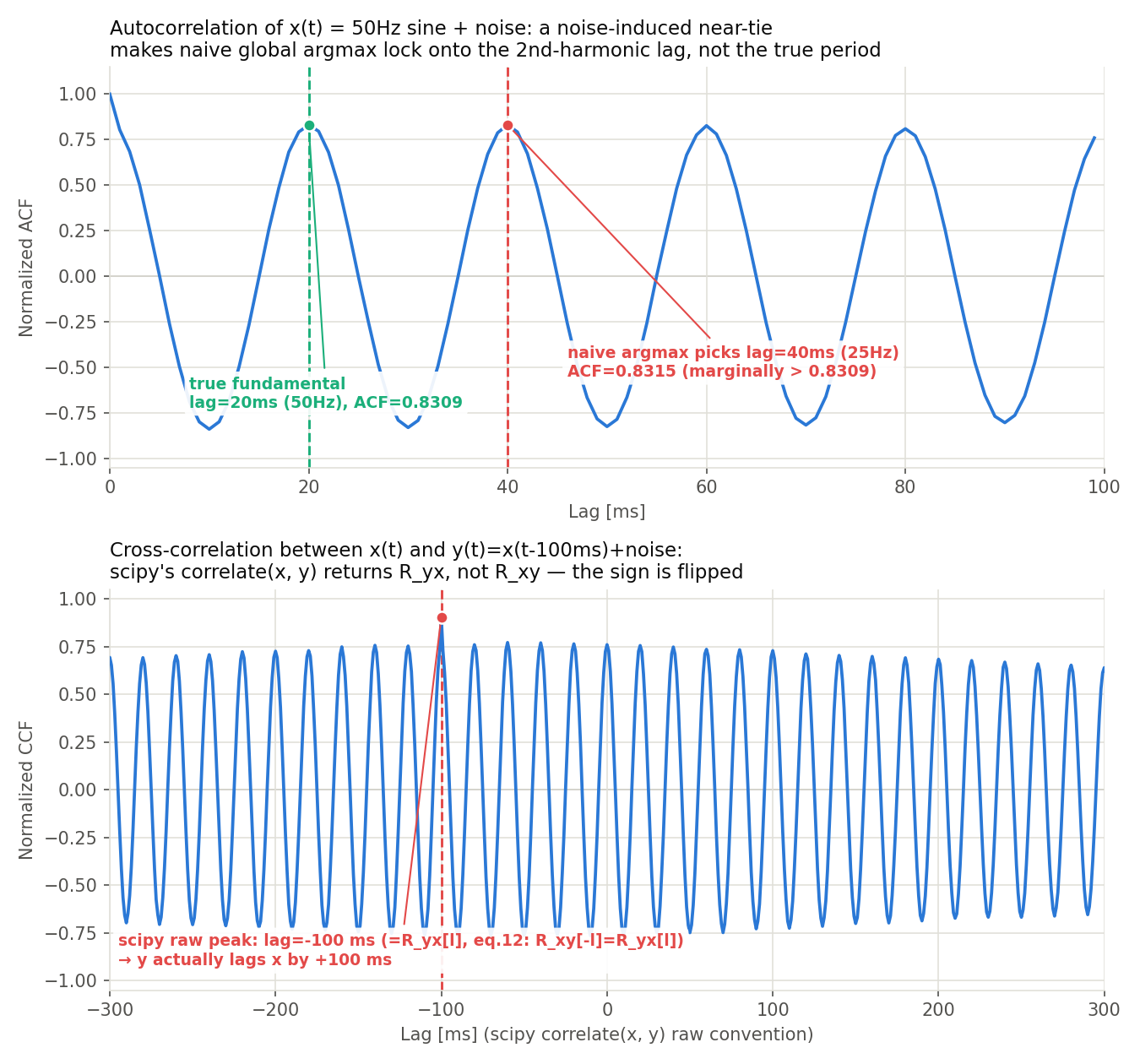
ACF first peak: lag=40.0 ms → frequency = 25.0 Hz
Cross-correlation peak: lag=-100.0 ms → delay = -100 samples
This looks odd at first glance. Signal x is a 50 Hz sine wave, so its period should be 20 ms, yet the detected peak is at 40 ms (25 Hz). And y was built by delaying x by 100 samples, yet the peak lag of the cross-correlation came out as -100, with the opposite sign. Neither of these is an implementation bug — they expose two important pitfalls: the effect of noise and the sign convention of scipy’s correlation.
Pitfall 1: a naive argmax locks onto a harmonic lag under noise
The plain argmax over acf[10:] picked lag 40 ms, with no relation to the true fundamental period (lag=20 ms). Inspecting the ACF values directly,
acf[20] = 0.8309  (peak at the true fundamental period)
acf[40] = 0.8315  (peak at the 2nd period; noise pushes it marginally higher)
the two values are nearly tied (differing by only 0.0006), and the noise generated with np.random.seed(42) happened to lift the second-period peak just slightly above the true one, so the global argmax mistakenly locked onto double the true period (half the true frequency). This is a textbook failure mode: implementing periodicity or pitch detection with a bare global argmax is vulnerable to picking an integer submultiple of the true fundamental (an octave error) whenever noise or harmonic structure creates a near-tie. This is exactly why the detect_periodicity function in the next section restricts its search window using zero crossings.
Pitfall 2: scipy.signal.correlate(x, y) returns \(R_{yx}\)
, not \(R_{xy}\)
The negative cross-correlation peak lag (-100) is likewise not a bug — it is precisely the symmetry of eq.(12),
showing up in practice. By definition, scipy.signal.correlate(in1, in2, mode='full') computes \(\sum_n \text{in2}[n] \cdot \text{in1}[n+l]\)
, i.e., in this article’s notation, correlate(x, y) computes \(R_{yx}[l]\)
, not \(R_{xy}[l]\)
. When y lags x by 100 samples, \(R_{xy}[l]\)
peaks at \(l=+100\)
(from eq.9–10), while by the symmetry above \(R_{yx}[l]\)
peaks at the sign-flipped \(l=-100\)
— exactly the -100 seen in the output. Whenever you infer “which signal leads” from the sign of an estimated delay, you must verify empirically which variable the library function treats as the reference for the correlation — the convention is not always the intuitive one.
Periodicity Detection with the ACF
import numpy as np
import matplotlib.pyplot as plt

def detect_periodicity(signal, fs, max_lag_sec=None):
    """
    Detect periodicity using the ACF.

    Parameters
    ----------
    signal : np.ndarray
        Input signal
    fs : float
        Sampling frequency [Hz]
    max_lag_sec : float, optional
        Maximum lag to analyze [s]. Defaults to half the signal length.

    Returns
    -------
    period_sec : float or None
        Detected period [s], or None if not found
    acf : np.ndarray
        Normalized ACF
    lags_sec : np.ndarray
        Lag values [s]
    """
    N = len(signal)
    max_lag = int(max_lag_sec * fs) if max_lag_sec else N // 2

    # FFT-based ACF
    X = np.fft.fft(signal, n=2*N)
    acf = np.fft.ifft(X * np.conj(X)).real[:N]
    acf = acf[:max_lag]
    acf_norm = acf / acf[0]
    lags_sec = np.arange(max_lag) / fs

    # Find the first peak one period ahead.
    # The ACF decays from lag 0 and first crosses zero at zero_cross[0],
    # then returns to positive at zero_cross[1] (note the interval
    # [0]-[1] is the *trough*, not a peak). The first true peak
    # corresponding to the fundamental period appears after the trough,
    # in the interval zero_cross[1]-zero_cross[2].
    zero_cross = np.where(np.diff(np.sign(acf_norm)))[0]
    if len(zero_cross) < 3:
        return None, acf_norm, lags_sec

    search_start = zero_cross[1] + 1
    search_end = zero_cross[2]
    peak_idx = search_start + np.argmax(acf_norm[search_start:search_end])
    period_sec = lags_sec[peak_idx]

    return period_sec, acf_norm, lags_sec


# --- Compare periodicity across multiple signals ---
fs = 1000
t = np.arange(0, 1.0, 1/fs)
np.random.seed(0)

signals = {
    '50 Hz Sine Wave': np.sin(2 * np.pi * 50 * t) + 0.2 * np.random.randn(len(t)),
    'Composite Sine Wave\n(50 + 130 Hz)': (np.sin(2 * np.pi * 50 * t)
                                   + 0.5 * np.sin(2 * np.pi * 130 * t)
                                   + 0.1 * np.random.randn(len(t))),
    'White Noise': np.random.randn(len(t)),
}

fig, axes = plt.subplots(len(signals), 2, figsize=(14, 10))

for i, (name, sig) in enumerate(signals.items()):
    period, acf, lags = detect_periodicity(sig, fs, max_lag_sec=0.15)
    if period:
        print(f"{name.strip()}: period={period*1000:.1f} ms → {1/period:.1f} Hz")
    else:
        print(f"{name.strip()}: no period detected")

    axes[i, 0].plot(t[:300], sig[:300])
    axes[i, 0].set_xlabel('Time [s]')
    axes[i, 0].set_ylabel('Amplitude')
    axes[i, 0].set_title(f'Signal: {name}')
    axes[i, 0].grid(True, alpha=0.3)

    axes[i, 1].plot(lags * 1000, acf)
    axes[i, 1].axhline(y=0, color='k', linestyle='--', linewidth=0.8)
    if period:
        axes[i, 1].axvline(x=period * 1000, color='r', linestyle='--',
                           label=f'Period={period*1000:.1f} ms\n→ {1/period:.1f} Hz')
        axes[i, 1].legend(fontsize=9)
    axes[i, 1].set_xlabel('Lag [ms]')
    axes[i, 1].set_ylabel('Normalized ACF')
    axes[i, 1].set_title('Autocorrelation')
    axes[i, 1].grid(True, alpha=0.3)

plt.tight_layout()
plt.show()
Execution result:
50 Hz Sine Wave: period=20.0 ms → 50.0 Hz
Composite Sine Wave(50 + 130 Hz): period=22.0 ms → 45.5 Hz
White Noise: period=5.0 ms → 200.0 Hz
The 50 Hz sine wave correctly detects a period of 20 ms (50 Hz). The key is searching between zero_cross[1] and zero_cross[2]. If instead we naively searched between zero_cross[0] and zero_cross[1] (the “trough” interval where the ACF first crosses zero and returns to zero), we would detect the edge of the trough rather than the peak, and even the pure 50 Hz signal would return a meaningless value such as period=6.0 ms (166.7 Hz). Not confusing the trough with the peak — shifting the zero-crossing window by one interval — is the crux of this implementation.
The composite sine wave (50 + 130 Hz) returns period=22.0 ms (45.5 Hz), off by 2 ms (10%) from the 20 ms period of the 50 Hz component. Superposition with the 130 Hz component distorts the ACF away from a simple cosine, shifting the location of the local maximum within the search window. Periodicity detection works well when a single frequency dominates, but when multiple frequency components are present at comparable strength, the ACF peak location can drift away from the exact period of any individual component (an FFT-based spectral analysis is more appropriate when precise frequency resolution is required).
White noise returns period=5.0 ms (200 Hz), but this is a spurious, meaningless peak. The theoretical ACF of white noise is a delta function (1 at lag 0, 0 elsewhere), but any finite-sample estimate (1000 samples here) retains statistical fluctuation, and the largest of the small bumps near zero gets picked up by chance. In production, a periodicity detector should check not only the detected period but also whether the peak height (ACF value) clears a significance threshold (such as the \(\pm 1.96/\sqrt{N}\)
bound discussed later).
Delay Estimation via Cross-Correlation (GCC-PHAT)
In microphone array applications such as sound source localization, the goal is to estimate the Time Difference of Arrival (TDOA) between signals captured by two microphones. GCC-PHAT (Generalized Cross-Correlation with Phase Transform) is widely used for this purpose because it achieves higher localization accuracy than simple cross-correlation.
\[\hat{R}^{\text{PHAT}}_{xy}[l] = \mathcal{F}^{-1}\left\{\frac{X^*(f) Y(f)}{|X^*(f) Y(f)|}\right\} \tag{16}\]By normalizing the amplitude spectrum in the denominator, the method reduces dependence on dominant frequency components and improves robustness to noise. Eq.(16) is the phase-only special case of the general FFT-based CCF expression in eq.(14), \(R_{xy}[l] = \mathcal{F}^{-1}\{X^*(f)Y(f)\}\) , so the conjugate is taken on \(X(f)\) here as well, to keep the convention consistent with eq.(14).
Note (convention differs across the literature): the original GCC-PHAT paper, Knapp & Carter (1976), uses the opposite convention \(G_{xy}(f) = X(f)Y^*(f)\) (conjugating \(Y\) instead). In this article’s notation (eq.9), that corresponds to \(R_{yx}\) , and by the symmetry of eq.(12) (\(R_{xy}\) and \(R_{yx}\) swap under a sign flip of the lag), the estimated delay comes out with the opposite sign. Both conventions are mathematically valid cross-correlations, but mixing which variable gets conjugated between an implementation and a reference silently flips the sign of the estimated delay — so, as demonstrated below, always validate the sign against synthetic data with a known delay.
import numpy as np
import matplotlib.pyplot as plt

def gcc_phat(x, y, fs, max_delay=None):
    """
    Delay estimation using GCC-PHAT.

    Parameters
    ----------
    x, y : np.ndarray
        Two input signals
    fs : float
        Sampling frequency [Hz]
    max_delay : float, optional
        Maximum delay to search [s]

    Returns
    -------
    delay_sec : float
        Estimated delay [s] (y lags x by delay_sec)
    cc : np.ndarray
        GCC-PHAT correlation values
    lags_sec : np.ndarray
        Lag values [s]
    """
    N = len(x) + len(y) - 1
    N_fft = 2 ** int(np.ceil(np.log2(N)))

    X = np.fft.fft(x, n=N_fft)
    Y = np.fft.fft(y, n=N_fft)

    # GCC-PHAT: use phase information only (conjugate X, consistent with eq.14/16)
    G = np.conj(X) * Y
    G_phat = G / (np.abs(G) + 1e-10)  # Numerical stabilization
    cc = np.fft.ifft(G_phat).real

    # Compute lags
    lags = np.fft.fftfreq(N_fft, d=1) * N_fft
    lags = lags.astype(int)

    # FFT-shift to center zero lag
    cc_shifted = np.fft.fftshift(cc)
    lags_shifted = np.fft.fftshift(lags)
    lags_sec = lags_shifted / fs

    if max_delay:
        mask = np.abs(lags_sec) <= max_delay
        cc_shifted = cc_shifted[mask]
        lags_sec = lags_sec[mask]

    peak_idx = np.argmax(cc_shifted)
    delay_sec = lags_sec[peak_idx]

    return delay_sec, cc_shifted, lags_sec


# --- Test ---
fs = 16000
t = np.arange(0, 0.5, 1/fs)
np.random.seed(7)

# Source signal
source = np.random.randn(len(t))
# Microphone 1: direct path
mic1 = source.copy() + 0.1 * np.random.randn(len(t))
# Microphone 2: actual delay (5 ms = 80 samples)
true_delay_samples = int(0.005 * fs)   # 80 samples
mic2 = np.zeros_like(mic1)
mic2[true_delay_samples:] = source[:-true_delay_samples] + 0.1 * np.random.randn(len(t) - true_delay_samples)

delay_est, cc, lags = gcc_phat(mic1, mic2, fs, max_delay=0.02)
print(f"True delay:        {true_delay_samples / fs * 1000:.2f} ms ({true_delay_samples} samples)")
print(f"GCC-PHAT estimate: {delay_est * 1000:.2f} ms ({int(delay_est * fs)} samples)")

plt.figure(figsize=(10, 4))
plt.plot(lags * 1000, cc)
plt.axvline(x=delay_est * 1000, color='r', linestyle='--',
            label=f'Estimated delay = {delay_est*1000:.2f} ms')
plt.axvline(x=true_delay_samples / fs * 1000, color='g', linestyle=':',
            label=f'True delay = {true_delay_samples/fs*1000:.2f} ms')
plt.xlabel('Lag [ms]')
plt.ylabel('GCC-PHAT')
plt.title('GCC-PHAT Cross-Correlation for TDOA Estimation')
plt.legend()
plt.grid(True, alpha=0.3)
plt.tight_layout()
plt.show()
Execution result:
True delay:        5.00 ms (80 samples)
GCC-PHAT estimate: 5.00 ms (80 samples)
With G = np.conj(X) * Y, kept consistent with eq.(14), the estimate lands exactly on the true delay of 5.00 ms (80 samples). If instead we run the Knapp & Carter (1976) convention noted above (G = X * np.conj(Y)), we get:
True delay:                5.00 ms (80 samples)
GCC-PHAT estimate (flipped convention): -5.00 ms (-80 samples)
— matching in magnitude, but flipped in sign. This is not a bug; it is exactly the symmetry of eq.(12) showing up numerically. In applications such as radar or microphone-array source localization, where the sign of the delay (which signal led) carries the meaning of the result, this is a strong reminder to always validate the sign convention against synthetic data with a known delay before trusting a production estimate.
TDOA estimation via GCC-PHAT remains an active research area. Berg et al. (2024) propose “NGCC-PHAT,” which replaces the phase-transform stage of GCC-PHAT with a learnable neural network, enabling TDOA estimation even when multiple sound sources overlap. Evaluated on the STARSS23 dataset for Sound Event Localization and Detection (SELD) at the DCASE 2024 workshop, it outperforms both standard GCC-PHAT features and SALSA-Lite. It is notable that the classical GCC-PHAT formula covered in this section is still very much alive today — as the “front-end” feature feeding into learnable localization networks.
Application: Speech Pitch Estimation (YIN Algorithm)
ACF-based pitch estimation is widely used in speech processing. The YIN algorithm (de Cheveigné & Kawahara, 2002) combines a difference function with the ACF to estimate pitch with high accuracy.
The difference function \(d[l]\) is defined as:
\[d[l] = \sum_{n=0}^{N-1} (x[n] - x[n+l])^2 \tag{17}\]Expanding this expression makes the relationship to autocorrelation explicit:
\[d[l] = 2R_{xx}[0] - 2R_{xx}[l] \tag{18}\]The Cumulative Mean Normalized Difference (CMND) derived from the difference function improves peak detection accuracy near zero crossings.
import numpy as np
import matplotlib.pyplot as plt

def yin_pitch(signal, fs, fmin=75, fmax=500, threshold=0.1):
    """
    Pitch estimation using the YIN algorithm (simplified).

    Returns
    -------
    f0 : float or None
        Estimated fundamental frequency [Hz]
    d_norm : np.ndarray
        Normalized difference function
    """
    N = len(signal)
    W = N // 2  # Search window

    # Difference function (fast computation via FFT)
    X = np.fft.fft(signal, n=2*N)
    acf = np.fft.ifft(X * np.conj(X)).real[:N]

    d = np.zeros(W)
    d[0] = 0
    for l in range(1, W):
        d[l] = 2 * acf[0] - 2 * acf[l]

    # Cumulative Mean Normalized Difference (CMND)
    d_norm = np.zeros(W)
    d_norm[0] = 1.0
    cumsum = 0.0
    for l in range(1, W):
        cumsum += d[l]
        d_norm[l] = d[l] / (cumsum / l)

    # Restrict to the valid pitch range
    lag_min = int(fs / fmax)
    lag_max = int(fs / fmin)

    # Find the first dip below the threshold
    f0 = None
    for l in range(lag_min, min(lag_max, W)):
        if d_norm[l] < threshold:
            # Parabolic interpolation for sub-sample accuracy
            if 0 < l < W - 1:
                alpha = d_norm[l-1]
                beta = d_norm[l]
                gamma = d_norm[l+1]
                delta = (alpha - gamma) / (2 * (alpha - 2*beta + gamma))
                l_refined = l + delta
            else:
                l_refined = l
            f0 = fs / l_refined
            break

    return f0, d_norm


# --- Test: synthetic voices at different pitches ---
fs = 16000
t = np.arange(0, 0.1, 1/fs)  # 100 ms frame

test_cases = {
    'Male Voice (120 Hz)': 120,
    'Female Voice (220 Hz)': 220,
    "Child's Voice (350 Hz)": 350,
}

fig, axes = plt.subplots(len(test_cases), 2, figsize=(14, 10))

for i, (label, f0_true) in enumerate(test_cases.items()):
    # Synthetic voice with harmonics
    np.random.seed(i)
    voice = (np.sin(2 * np.pi * f0_true * t)
             + 0.5 * np.sin(2 * np.pi * 2 * f0_true * t)
             + 0.3 * np.sin(2 * np.pi * 3 * f0_true * t)
             + 0.05 * np.random.randn(len(t)))

    f0_est, d_norm = yin_pitch(voice, fs)
    print(f"{label}: true F0={f0_true} Hz, estimated F0={f0_est:.2f} Hz, "
          f"error={f0_est - f0_true:+.2f} Hz ({(f0_est - f0_true) / f0_true * 100:+.2f}%)")

    axes[i, 0].plot(t * 1000, voice)
    axes[i, 0].set_xlabel('Time [ms]')
    axes[i, 0].set_ylabel('Amplitude')
    axes[i, 0].set_title(f'{label}: True F0 = {f0_true} Hz')
    axes[i, 0].grid(True, alpha=0.3)

    lag_ms = np.arange(len(d_norm)) / fs * 1000
    axes[i, 1].plot(lag_ms, d_norm)
    axes[i, 1].axhline(y=0.1, color='r', linestyle='--', label='threshold=0.1')
    if f0_est:
        axes[i, 1].axvline(x=1000/f0_est, color='g', linestyle='--',
                           label=f'Est. F0 = {f0_est:.1f} Hz')
    axes[i, 1].set_xlabel('Lag [ms]')
    axes[i, 1].set_ylabel('Normalized d[l]')
    axes[i, 1].set_title('YIN: Cumulative Mean Normalized Difference')
    axes[i, 1].set_xlim(0, 30)
    axes[i, 1].legend(fontsize=9)
    axes[i, 1].grid(True, alpha=0.3)

plt.tight_layout()
plt.show()
Execution result:
Male Voice (120 Hz): true F0=120 Hz, estimated F0=120.09 Hz, error=+0.09 Hz (+0.07%)
Female Voice (220 Hz): true F0=220 Hz, estimated F0=218.98 Hz, error=-1.02 Hz (-0.47%)
Child's Voice (350 Hz): true F0=350 Hz, estimated F0=348.34 Hz, error=-1.66 Hz (-0.48%)
All three cases are estimated to well under 1% error, but the absolute error grows with the pitch (child’s voice, 350 Hz, has the largest). At fs=16000 Hz with fmax=500 Hz, a higher pitch corresponds to a shorter lag (fs/f0), so the integer-lag spacing available for the parabolic interpolation becomes coarser (the relative error of the sub-sample interpolation increases). In practice, the frame length, sampling rate, and search range for the pitch must be tuned to the target voice band.
More than two decades after its introduction, YIN remains a standard baseline in speech processing, but self-supervised deep-learning pitch estimators are increasingly displacing it. Riou et al. (2023) propose PESTO (Pitch Estimation with Self-supervised Transposition-equivariant Objective, ISMIR 2023 Best Paper), a lightweight neural network (under 30k parameters) trained with a self-supervised, transposition-equivariant objective over the CQT (Constant-Q Transform). Compared against YIN and CREPE, it achieves competitive accuracy from unlabeled data alone while running more than 12x faster than real time. It is telling that YIN, a deterministic ACF-based algorithm, is still cited as the baseline against which deep-learning pitch estimators are benchmarked — a testament to the continued practical relevance of the theory covered in this article.
Application: Time-Series Analysis (ARIMA Order Selection)
In time-series analysis, the ACF and Partial Autocorrelation Function (PACF) are the primary tools for determining the order of an ARIMA model:
\[\text{PACF}(k) = \text{Corr}(x_t, x_{t-k} \mid x_{t-1}, \ldots, x_{t-k+1}) \tag{19}\]The PACF represents the pure correlation at lag \(k\) after removing the influence of all intermediate lags.
import numpy as np
import matplotlib.pyplot as plt
from statsmodels.tsa.stattools import acf, pacf
from statsmodels.graphics.tsaplots import plot_acf, plot_pacf

# --- Simulate an AR(2) process ---
# x[t] = 0.7 * x[t-1] - 0.3 * x[t-2] + noise
np.random.seed(42)
N = 300
phi = [0.7, -0.3]   # AR coefficients
noise_std = 1.0

x = np.zeros(N)
for t in range(2, N):
    x[t] = phi[0] * x[t-1] + phi[1] * x[t-2] + np.random.randn() * noise_std

# Compute ACF and PACF
nlags = 20
acf_vals = acf(x, nlags=nlags, fft=True)
pacf_vals = pacf(x, nlags=nlags)

# Confidence interval (approximate: ±1.96/√N)
ci = 1.96 / np.sqrt(N)

fig, axes = plt.subplots(3, 1, figsize=(12, 10))

# Time-series plot
axes[0].plot(x)
axes[0].set_xlabel('Time step')
axes[0].set_ylabel('x[t]')
axes[0].set_title('AR(2) Process: x[t] = 0.7·x[t-1] − 0.3·x[t-2] + noise')
axes[0].grid(True, alpha=0.3)

# ACF plot
lags = np.arange(nlags + 1)
axes[1].bar(lags, acf_vals, color='steelblue', alpha=0.7)
axes[1].axhline(y=ci, color='r', linestyle='--', linewidth=0.8, label='±95% CI')
axes[1].axhline(y=-ci, color='r', linestyle='--', linewidth=0.8)
axes[1].axhline(y=0, color='k', linewidth=0.5)
axes[1].set_xlabel('Lag')
axes[1].set_ylabel('ACF')
axes[1].set_title('Autocorrelation Function (ACF): Gradual decay → AR process')
axes[1].legend()
axes[1].grid(True, alpha=0.3)

# PACF plot
axes[2].bar(lags, pacf_vals, color='coral', alpha=0.7)
axes[2].axhline(y=ci, color='r', linestyle='--', linewidth=0.8, label='±95% CI')
axes[2].axhline(y=-ci, color='r', linestyle='--', linewidth=0.8)
axes[2].axhline(y=0, color='k', linewidth=0.5)
axes[2].set_xlabel('Lag')
axes[2].set_ylabel('PACF')
axes[2].set_title('Partial ACF (PACF): Cuts off after lag 2 → confirms AR(2)')
axes[2].legend()
axes[2].grid(True, alpha=0.3)

plt.tight_layout()
plt.show()

print(f"PACF(1) = {pacf_vals[1]:.3f} (true value: φ₁ = {phi[0]})")
print(f"PACF(2) = {pacf_vals[2]:.3f} (true value: φ₂ = {phi[1]})")
print(f"PACF(3) = {pacf_vals[3]:.3f} (cutoff: close to 0)")
Execution result:
PACF(1) = 0.486 (true value: φ₁ = 0.7)
PACF(2) = -0.291 (true value: φ₂ = -0.3)
PACF(3) = -0.031 (cutoff: close to 0)
The 95% confidence interval is \(\pm 1.96/\sqrt{300} = \pm 0.113\) . Both PACF(1)=0.486 and PACF(2)=-0.291 lie well outside this band and are statistically significant, while PACF(3)=-0.031 falls inside it, confirming the cutoff. This is exactly the signature of an AR(2) process — the PACF is theoretically zero beyond the true order.
At the same time, while PACF(2)=-0.291 is close to the true value \(\phi_2=-0.3\)
, PACF(1)=0.486 undershoots the true value \(\phi_1=0.7\)
by nearly 30%. This is not an implementation bug but sampling variability from the finite sample size \(N=300\)
. Indeed, this process’s characteristic equation \(z^2 - 0.7z + 0.3 = 0\)
has a negative discriminant (\(0.49 - 1.2 = -0.71 < 0\)
), meaning it has complex-conjugate roots: the theoretical ACF is not a simple monotonic decay but a damped oscillation (acf_vals[:5] = [1.000, 0.484, 0.014, -0.153, -0.130] is likewise non-monotonic). The qualitative decision of order selection — at which lag the PACF cuts off — is robust, but the point estimates of the coefficients themselves can deviate from the true values under finite samples. Once the order is fixed, re-estimating the coefficients via maximum likelihood is the standard next step in practice.
The exponential decay of the ACF without a sharp cutoff, combined with the PACF cutting off after lag 2, confirms that this process is AR(2).
Summary of Key Applications
| Application | Correlation Used | Key Feature |
|---|---|---|
| Periodicity detection | ACF | Fundamental period estimated from peak lag |
| Pitch estimation (speech) | ACF (YIN, etc.) | Extracts the fundamental frequency (F0) of the voice |
| TDOA estimation (microphone arrays) | CCF (GCC-PHAT) | Sound source localization from time difference of arrival |
| Template matching | CCF | Locating similar patterns in images and signals |
| ARIMA order selection | ACF + PACF | Choosing the \(p\) and \(q\) orders |
| White noise test | ACF | Verifying randomness of model residuals |
| Radar / sonar | CCF | Distance estimation from reflected signal delay |
Summary
- The autocorrelation function (ACF) measures the similarity between a signal and its time-shifted copy, making it effective for detecting periodicity and repetitive structure.
- The Wiener–Khinchin theorem establishes that the Fourier transform of the ACF equals the power spectral density (PSD), demonstrating the equivalence of time-domain and frequency-domain analysis.
- The cross-correlation function (CCF) is used to estimate delays and quantify similarity between two signals; GCC-PHAT is its noise-robust variant widely applied in sound source localization.
- FFT-based fast computation (\(O(N \log N)\) ) dramatically reduces computational cost compared to direct calculation (\(O(N^2)\) ).
- Using ACF and PACF together to determine the order of an ARIMA model is a standard procedure in time-series analysis.
- The YIN algorithm leverages the relationship between the difference function and the ACF to achieve high-accuracy pitch estimation.
Related Articles
- Advanced: PACF and AR Model Order Identification - The companion to this article’s ACF: partial autocorrelation (PACF) theory and the practical procedure for identifying the AR order \(p\) .
- Fast Fourier Transform (FFT): How It Works and Python Implementation - Covers the DFT/FFT fundamentals underlying FFT-based correlation computation.
- Window Functions and Power Spectral Density (PSD): Theory and Python Implementation - Explains Welch’s method for PSD estimation, closely related to the Wiener–Khinchin theorem.
- Short-Time Fourier Transform (STFT): Theory and Python Implementation - Covers STFT for frequency analysis of time-varying signals.
- Cepstrum Analysis: Theory and Python Implementation - Explains cepstrum-based F0 estimation, an alternative approach related to the ACF.
- Time-Series Forecasting with ARIMA - Covers ARIMA model order selection using ACF/PACF and practical time-series forecasting.
- Wavelet Transform: Theory and Python Implementation - A complementary time-frequency analysis approach to autocorrelation.
- Hilbert Transform and Instantaneous Frequency Analysis - Extracting instantaneous frequency to analyze time-varying frequency components.
- Time-Series Anomaly Detection - Anomaly detection methods including stationarity tests and residual analysis using the ACF.
- Convolution and Correlation: Theory and Python Implementation - Articulates the convolution-correlation relationship (time-reversal) and the Wiener-Khinchin foundation.
- Sampling Theorem and Aliasing - The discretisation step that ACF computation presupposes, including the Nyquist condition.
- DTFT, DFT, and FFT: Putting the Hierarchy in Order - Theoretical foundation for FFT-based fast autocorrelation and the Wiener-Khinchin / DFT relationship.
- Z-Transform and Digital Filter Transfer Functions - LTI-system transfer-function view of the processes that generate autocorrelation structure.
- Discrete Cosine Transform (DCT) - An alternative feature representation to ACF based on DCT coefficients.
- Time-Frequency Analysis Guide - Hub overview of time-frequency methods including ACF and PSD.
- ML x Time-Series Guide - From ACF/PACF to ARIMA, state-space models, and deep learning.
- DSP x ML Roadmap - Meta-roadmap placing autocorrelation in the DSP-to-ML pipeline.
- Discrete DSP Fundamentals Roadmap - A hub bundling sampling, interpolation, DFT, Z-transform, autocorrelation, and DCT. Autocorrelation is a core piece of the math operations on discrete signals.
- Transformer for time-series forecasting: self-attention, positional encoding, Informer - Self-attention is a weighted sum where the weights are inner products between a query and all keys — it can be read as a learned, multi-lag generalization of the ACF. Autoformer’s Auto-Correlation block is a literal modulization of the ACF defined in this article.
- Teager-Kaiser Energy Operator (TKEO) in Python - In contrast to the ACF’s window-averaged estimate, TKEO is a lightweight nonlinear operator that estimates instantaneous energy from just a 3-point difference.
References
- de Cheveigné, A., & Kawahara, H. (2002). “YIN, a fundamental frequency estimator for speech and music.” Journal of the Acoustical Society of America, 111(4), 1917–1930.
- Knapp, C. H., & Carter, G. C. (1976). “The generalized correlation method for estimation of time delay.” IEEE Transactions on Acoustics, Speech, and Signal Processing, 24(4), 320–327.
- Box, G. E. P., Jenkins, G. M., Reinsel, G. C., & Ljung, G. M. (2015). Time Series Analysis: Forecasting and Control (5th ed.). Wiley.
- Oppenheim, A. V., & Schafer, R. W. (2009). Discrete-Time Signal Processing (3rd ed.). Prentice Hall.
- Riou, A., Lattner, S., Hadjeres, G., & Peeters, G. (2023). “PESTO: Pitch Estimation with Self-supervised Transposition-equivariant Objective.” Proceedings of the 24th International Society for Music Information Retrieval Conference (ISMIR 2023). (Best Paper Award) arXiv:2309.02265
- Berg, A., Engman, J., Gulin, J., Åström, K., & Oskarsson, M. (2024). “Learning Multi-Target TDOA Features for Sound Event Localization and Detection.” DCASE 2024 Workshop. arXiv:2408.17166
- SciPy signal.correlate documentation
- Statsmodels ACF/PACF documentation