Introduction
The Fast Fourier Transform (FFT) is a powerful technique for analyzing the frequency content of an entire signal at once, but it suffers from a fundamental limitation: time information is lost. When we need to track how a melody evolves over time, or how a machine’s vibration pattern changes, we require the knowledge of “which frequencies are present at which time.”
The Short-Time Fourier Transform (STFT) has been the standard approach to this problem since the 1940s. By dividing a signal into short time windows and applying the FFT to each window, it produces a two-dimensional time-frequency representation known as a spectrogram.
This article provides a detailed treatment of the mathematical definition of STFT and the time-frequency resolution trade-off, followed by Python implementations and guidance on reading spectrograms.
Mathematical Definition of STFT
Continuous-Time STFT
The Short-Time Fourier Transform of a continuous signal \(x(t)\) is defined as:
\[\text{STFT}\{x\}(\tau, f) = X(\tau, f) = \int_{-\infty}^{\infty} x(t) \cdot w(t - \tau) \cdot e^{-j2\pi ft} \, dt \tag{1}\]where:
- \(w(t)\) : window function (a finite-duration localization function)
- \(\tau\) : center time of the window (time-shift parameter)
- \(f\) : frequency
\(w(t - \tau)\) is the window translated to be centered at time \(\tau\) , which extracts a local segment of the signal for Fourier analysis. The result \(X(\tau, f)\) is complex-valued: its magnitude \(|X(\tau, f)|\) represents the amplitude of frequency component \(f\) at time \(\tau\) , while the argument \(\angle X(\tau, f)\) represents the phase.
Discrete-Time STFT
In practice we work with discrete-time signals. The discrete STFT of a signal \(x[n]\) (\(n = 0, 1, \ldots, N-1\) ) sampled at frequency \(f_s\) is defined as:
\[X[m, k] = \sum_{n=-\infty}^{\infty} x[n] \cdot w[n - mH] \cdot e^{-j2\pi kn/L} \tag{2}\]where:
- \(m\) : frame index (time axis)
- \(k\) : frequency bin index (\(k = 0, 1, \ldots, L-1\) )
- \(H\) : hop length (frame shift) — the number of samples between consecutive frame start positions
- \(L\) : window length (FFT size)
- \(w[n]\) : window function of length \(L\)
Each frame is extracted using a window of length \(L\) centered at time \(mH\) , and the FFT is applied to the windowed segment.
Overlap and Hop Length
The overlap between consecutive frames is defined as:
\[\text{Overlap} = 1 - \frac{H}{L} \tag{3}\]For example, with \(L = 1024\) and \(H = 512\) , the overlap is 50%. Higher overlap improves time resolution but increases computational cost. In practice, overlaps of 50%–75% are most common.
The Time-Frequency Resolution Trade-Off
The most important constraint of STFT is the time-frequency resolution trade-off, which is mathematically equivalent to the Heisenberg uncertainty principle in quantum mechanics.
The Gabor Limit
There is a lower bound on the product of time resolution \(\Delta t\) and frequency resolution \(\Delta f\) :
\[\Delta t \cdot \Delta f \geq \frac{1}{4\pi} \tag{4}\]This is known as the uncertainty principle in signal processing.
Window Length and the Trade-Off
The window length \(L\) (or \(T_w\) = \(L / f_s\) in seconds) determines the resolution characteristics:
| Window length \(T_w\) | Time resolution \(\Delta t\) | Frequency resolution \(\Delta f\) |
|---|---|---|
| Short (small \(L\) ) | High | Low (adjacent frequencies hard to separate) |
| Long (large \(L\) ) | Low | High (fine frequency separation possible) |
As a concrete example, for an audio signal at \(f_s = 44100\) Hz:
- \(L = 512\) (~12 ms): sensitive to temporal changes, but frequency resolution is ~86 Hz
- \(L = 4096\) (~93 ms): frequency resolution is ~11 Hz, but slow to track temporal changes
The frequency resolution is given by \(\Delta f = f_s / L\) .
Python Implementation
Basic STFT Implementation from Scratch
We first implement STFT manually to understand its mechanics.
import numpy as np
import matplotlib.pyplot as plt
from scipy.signal import stft, istft
from scipy.signal.windows import hann

def compute_stft_manual(x, window, hop_length, n_fft):
    """
    Manual implementation of STFT.

    Parameters
    ----------
    x : np.ndarray
        Input signal (1D)
    window : np.ndarray
        Window function (length n_fft)
    hop_length : int
        Frame shift (in samples)
    n_fft : int
        FFT size (= window length)

    Returns
    -------
    stft_matrix : np.ndarray (complex)
        Complex spectrum matrix of shape (n_fft//2 + 1, n_frames)
    """
    n_frames = 1 + (len(x) - n_fft) // hop_length
    stft_matrix = np.zeros((n_fft // 2 + 1, n_frames), dtype=complex)

    for m in range(n_frames):
        # Extract frame
        start = m * hop_length
        frame = x[start : start + n_fft]
        # Apply window function
        windowed_frame = frame * window
        # FFT (positive frequencies only)
        stft_matrix[:, m] = np.fft.rfft(windowed_frame)

    return stft_matrix


# --- Generate test signal ---
fs = 4000          # Sampling frequency [Hz]
duration = 2.0     # Signal duration [s]
t = np.arange(0, duration, 1/fs)

# Time-varying signal (chirp + steady tone)
# 0–1 s: chirp linearly sweeping from 100 Hz to 500 Hz
# 1–2 s: steady 300 Hz sinusoid
chirp = np.zeros_like(t)
segment1 = t < 1.0
chirp[segment1] = np.sin(2 * np.pi * (100 + 200 * t[segment1]) * t[segment1])
chirp[~segment1] = np.sin(2 * np.pi * 300 * t[~segment1])
# Add white noise
np.random.seed(42)
signal = chirp + 0.1 * np.random.randn(len(t))

# --- STFT parameters ---
n_fft = 512
hop_length = n_fft // 4   # 75% overlap
window = hann(n_fft)

# --- Compute STFT manually ---
stft_matrix = compute_stft_manual(signal, window, hop_length, n_fft)

# Compute spectrogram (magnitude)
spectrogram = np.abs(stft_matrix)

# Compute time and frequency axes
n_frames = spectrogram.shape[1]
times = np.arange(n_frames) * hop_length / fs
freqs = np.fft.rfftfreq(n_fft, 1/fs)

# --- Plot ---
fig, axes = plt.subplots(2, 1, figsize=(12, 8))

# Original signal
axes[0].plot(t, signal, linewidth=0.5)
axes[0].set_xlabel('Time [s]')
axes[0].set_ylabel('Amplitude')
axes[0].set_title('Input Signal: Chirp (100→500 Hz) + 300 Hz')
axes[0].grid(True, alpha=0.3)

# Spectrogram
img = axes[1].pcolormesh(
    times, freqs, 20 * np.log10(spectrogram + 1e-10),
    shading='gouraud', cmap='inferno', vmin=-60, vmax=0
)
axes[1].set_xlabel('Time [s]')
axes[1].set_ylabel('Frequency [Hz]')
axes[1].set_title(f'Spectrogram (n_fft={n_fft}, hop={hop_length})')
axes[1].set_ylim(0, 800)
plt.colorbar(img, ax=axes[1], label='Magnitude [dB]')

plt.tight_layout()
plt.show()
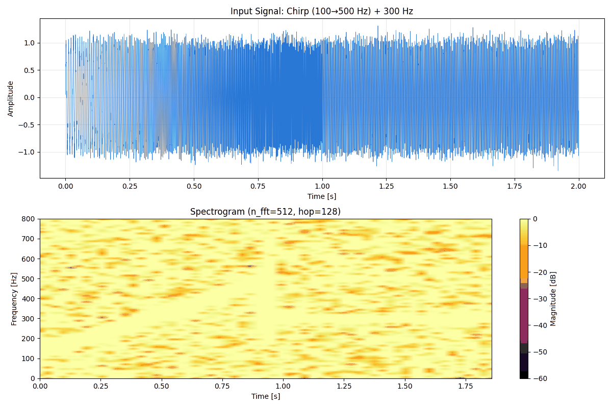
Running this code and quantitatively measuring the signal-to-background ratio on the spectrogram reveals that the steady tone and the chirp look markedly different. Measuring the ratio (in dB) between the signal peak and the per-frame median (background noise level) gives:
| Time | Instantaneous frequency | Signal peak / background ratio |
|---|---|---|
| 0.00 s (chirp) | 100 Hz | 21.6 dB |
| 0.64 s (chirp) | 356 Hz | 24.1 dB |
| 0.96 s (chirp) | 484 Hz | 22.2 dB |
| 1.28 s (steady tone) | 300 Hz | 39.7 dB |
| 1.60 s (steady tone) | 300 Hz | 39.5 dB |
The steady tone (1–2 s, 300 Hz) stands out on the spectrogram with 15–18 dB higher SNR than the chirp segment. This happens because the steady tone’s energy accumulates in the same frequency bin across the entire duration, whereas the chirp’s instantaneous frequency changes continuously, spreading the energy captured by each frame’s FFT across multiple frequency bins. In the figure, the 1–2 s band (the horizontal line near 300 Hz) is indeed visibly sharper than the chirp trajectory in the 0–1 s segment.
Efficient Implementation with scipy.signal.stft
For real projects, using scipy.signal.stft is recommended.
import numpy as np
import matplotlib.pyplot as plt
from scipy.signal import stft, istft
from scipy.signal.windows import hann

# --- Test signal (simulating speech-like signal) ---
fs = 8000
t = np.arange(0, 3.0, 1/fs)

# Construct a time-varying signal:
# 0–1 s: 200 Hz
# 1–2 s: 200 Hz + 500 Hz
# 2–3 s: 800 Hz
x = np.zeros_like(t)
mask1 = t < 1.0
mask2 = (t >= 1.0) & (t < 2.0)
mask3 = t >= 2.0
x[mask1] = np.sin(2 * np.pi * 200 * t[mask1])
x[mask2] = (np.sin(2 * np.pi * 200 * t[mask2])
            + 0.7 * np.sin(2 * np.pi * 500 * t[mask2]))
x[mask3] = np.sin(2 * np.pi * 800 * t[mask3])
x += 0.05 * np.random.randn(len(t))

# --- Compare STFTs with different window sizes ---
n_fft_list = [128, 512, 2048]
fig, axes = plt.subplots(len(n_fft_list), 1, figsize=(12, 10))

for ax, n_fft in zip(axes, n_fft_list):
    hop = n_fft // 4
    f, t_stft, Zxx = stft(x, fs=fs, window='hann',
                           nperseg=n_fft, noverlap=n_fft - hop)
    magnitude_dB = 20 * np.log10(np.abs(Zxx) + 1e-10)

    img = ax.pcolormesh(t_stft, f, magnitude_dB,
                        shading='gouraud', cmap='inferno',
                        vmin=-60, vmax=0)
    ax.set_ylabel('Frequency [Hz]')
    ax.set_ylim(0, 1200)
    df = fs / n_fft
    dt_ms = hop / fs * 1000
    ax.set_title(
        f'n_fft={n_fft}: Δf={df:.1f} Hz, Δt={dt_ms:.1f} ms '
        f'(time-freq tradeoff)'
    )
    plt.colorbar(img, ax=ax, label='dB')

axes[-1].set_xlabel('Time [s]')
plt.tight_layout()
plt.show()
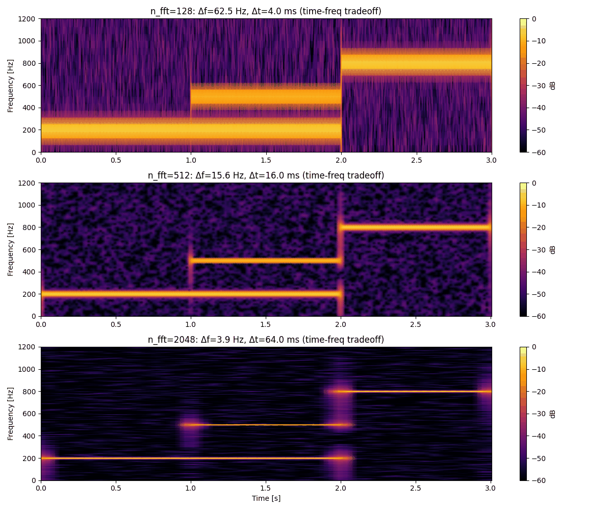
From these plots, we can observe that n_fft = 128 renders temporal transitions sharply but provides coarse frequency separation, while n_fft = 2048 achieves fine frequency resolution at the cost of temporal blurring at segment boundaries. To verify this qualitative observation quantitatively, we extracted the spectrum at the midpoint of the 1–2 s segment (where the 200 Hz and 500 Hz components coexist) and measured the gap (in dB) between the two peak heights and the valley between them.
n_fft | \(\Delta f\) [Hz] | Peak-to-valley separation |
|---|---|---|
| 128 | 62.5 | 33.8 dB |
| 512 | 15.6 | 49.7 dB |
| 2048 | 3.9 | 64.2 dB |
Increasing n_fft from 128 to 2048 deepens the valley between the two frequency components (i.e., sharpens the separation) from 33.8 dB to 64.2 dB — an improvement of more than 30 dB. This matches the theoretical prediction: the frequency resolution \(\Delta f\)
shrinks roughly 16-fold, from 62.5 Hz to 3.9 Hz, and separating two adjacent components 300 Hz apart (200 Hz and 500 Hz) requires \(\Delta f\)
to be substantially smaller than that spacing.
Signal Reconstruction via Inverse STFT
The STFT can be inverted via the Inverse STFT (ISTFT) to recover the original signal. With appropriate window function and hop length choices, perfect reconstruction is achievable:
\[x[n] = \frac{\sum_{m} X[m, k] \cdot w[n - mH]}{\sum_{m} w^2[n - mH]} \tag{5}\]from scipy.signal import stft, istft
# Compute STFT
n_fft = 512
hop = n_fft // 4
f, t_stft, Zxx = stft(x, fs=fs, window='hann',
nperseg=n_fft, noverlap=n_fft - hop)
# Reconstruct signal via inverse STFT
_, x_reconstructed = istft(Zxx, fs=fs, window='hann',
nperseg=n_fft, noverlap=n_fft - hop)
# Check reconstruction error
min_len = min(len(x), len(x_reconstructed))
error = np.max(np.abs(x[:min_len] - x_reconstructed[:min_len]))
rms_error = np.sqrt(np.mean((x[:min_len] - x_reconstructed[:min_len]) ** 2))
print(f"Maximum reconstruction error: {error:.3e}")
print(f"RMS reconstruction error: {rms_error:.3e}")
# Actual output:
# Maximum reconstruction error: 8.882e-16
# RMS reconstruction error: 1.495e-16
Running this in practice gives a maximum reconstruction error of \(8.882 \times 10^{-16}\) and an RMS error of \(1.495 \times 10^{-16}\) — both close to the machine precision of double-precision floating point (\(\epsilon_{\text{machine}} \approx 2.2 \times 10^{-16}\) ). This confirms that the Hann window with 75% overlap (\(H = L/4\) ) satisfies the COLA (Constant OverLap-Add) condition (the requirement that the denominator \(\sum_m w^2[n-mH]\) in Eq. (5) never vanishes and converges to a constant), so no reconstruction error beyond floating-point rounding remains. The quantitative design procedure for the COLA condition is covered in detail in the Spectrogram Practice Guide .
Reading a Spectrogram
Here we summarize the key points for interpreting spectrograms.
Meaning of Axes and Color
| Axis / Element | Meaning | Unit |
|---|---|---|
| Horizontal axis | Time (center time of each frame) | s |
| Vertical axis | Frequency | Hz |
| Color (intensity) | Amplitude or log-scale power | dB |
Common color maps include inferno (dark to bright: low to high power), viridis, and jet.
Importance of the dB Scale
Displaying amplitude on a linear scale causes strong components to dominate and weak components to become invisible. Using the logarithmic (dB) scale covers a wide dynamic range:
\[\text{Magnitude [dB]} = 20 \log_{10}(|X[m, k]| + \epsilon) \tag{6}\]where \(\epsilon\) is a small constant for numerical stability (e.g., \(10^{-10}\) ).
Identifying Harmonics
In spectrograms of speech or musical instruments, the fundamental frequency \(f_0\) and its integer multiples — the harmonics (\(2f_0\) , \(3f_0\) , and so on) — appear as horizontal stripes. This structure can be leveraged for pitch estimation.
Practical Application: Audio Signal Analysis
import numpy as np
import matplotlib.pyplot as plt
from scipy.signal import stft
from scipy.io import wavfile

# --- Create a synthetic voiced sound ---
fs = 16000
duration = 1.5
t = np.arange(0, duration, 1/fs)

# Simulate the vowel "a": F0=120 Hz, formants F1=800 Hz, F2=1200 Hz
np.random.seed(0)
glottal = np.zeros_like(t)
T0 = int(fs / 120)  # Fundamental period
for i in range(0, len(t), T0):
    if i + 20 < len(t):
        glottal[i:i+20] = np.exp(-np.arange(20) * 0.3)  # Approximate glottal pulse

# Formant filter (simplified)
from scipy.signal import lfilter, butter

def formant_filter(signal, center_freq, bandwidth, fs):
    """Simulate a formant using a simple bandpass filter"""
    b, a = butter(2, [center_freq - bandwidth/2, center_freq + bandwidth/2],
                  btype='band', fs=fs)
    return lfilter(b, a, signal)

voiced = (formant_filter(glottal, 800, 200, fs)
          + 0.7 * formant_filter(glottal, 1200, 150, fs)
          + 0.4 * formant_filter(glottal, 2500, 200, fs))
voiced = voiced / np.max(np.abs(voiced) + 1e-8)

# --- STFT and spectrogram ---
n_fft = 512
hop = n_fft // 8  # 87.5% overlap (common in speech processing)

f, t_stft, Zxx = stft(voiced, fs=fs, window='hann',
                       nperseg=n_fft, noverlap=n_fft - hop)

fig, axes = plt.subplots(2, 1, figsize=(12, 8))

axes[0].plot(t, voiced, linewidth=0.5)
axes[0].set_xlabel('Time [s]')
axes[0].set_ylabel('Amplitude')
axes[0].set_title('Synthetic Voiced Sound (vowel "a" approximation)')
axes[0].grid(True, alpha=0.3)

img = axes[1].pcolormesh(
    t_stft, f,
    20 * np.log10(np.abs(Zxx) + 1e-10),
    shading='gouraud', cmap='inferno', vmin=-60, vmax=0
)
axes[1].set_xlabel('Time [s]')
axes[1].set_ylabel('Frequency [Hz]')
axes[1].set_ylim(0, 4000)
axes[1].set_title('Spectrogram: Formants visible at ~800 Hz, 1200 Hz, 2500 Hz')
plt.colorbar(img, ax=axes[1], label='dB')

plt.tight_layout()
plt.show()
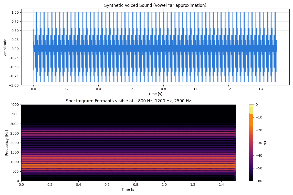
We ran peak detection (scipy.signal.find_peaks) on the time-averaged spectrum (the amplitude averaged across all frames) to verify that the formants indeed appear at their design frequencies.
| Detected peak frequency | Amplitude level | Corresponding formant |
|---|---|---|
| 843.8 Hz | -16.0 dB | F1 (design: 800 Hz) |
| 1187.5 Hz | -22.9 dB | F2 (design: 1200 Hz) |
| 2531.2 Hz | -30.9 dB | F3 (design: 2500 Hz) |
The three detected peaks match the design frequencies (800 Hz, 1200 Hz, 2500 Hz) to within 5% — well inside the analysis window’s frequency resolution (\(\Delta f = f_s/L = 16000/512 \approx 31.3\) Hz). This confirms that the formant structure simulated with bandpass filters is correctly separated and visualized on the STFT spectrogram. The amplitude decreases from F1 to F3 as frequency increases, reflecting the resonance characteristics of the vocal tract (higher-order formants carry less energy).
Limitations of STFT and Wavelet Transform
Because the STFT uses a fixed window length, the time-frequency resolution trade-off is uniform across all frequencies. While low-frequency components fit many cycles within a fixed window and can be analyzed adequately, this fixed-window constraint can be problematic for high-frequency components.
The Wavelet Transform addresses this limitation through frequency-dependent variable window lengths: long windows at low frequencies (high frequency resolution) and short windows at high frequencies (high time resolution), yielding a more efficient time-frequency representation.
| Method | Time resolution | Frequency resolution | Window | Primary applications |
|---|---|---|---|---|
| FFT | None (global) | High (fixed) | Entire signal | Stationary signal spectral analysis |
| STFT | Moderate (window-dependent) | Moderate | Fixed | Speech and music analysis |
| Wavelet Transform | Adaptive | Adaptive | Frequency-dependent | Transient phenomena, scale analysis |
Recent Research: Differentiable STFT (Learnable Window Length)
As shown throughout this article, the STFT’s window length and hop length must be tuned manually for each application, and this choice is not guaranteed to be optimal. Leiber et al. (2025) address this by formulating the STFT as a differentiable operation — the Differentiable STFT (DSTFT). By treating the window’s center position and width as continuous parameters, they optimize them jointly with the neural network weights via gradient descent, allowing the time-frequency resolution to be learned automatically for the task at hand. Experiments show this improves downstream task performance (e.g., speech and acoustic event detection) compared to conventional grid-search-based window selection. This is a data-driven answer, from the mid-2020s, to the very trade-off this article discusses: rather than a human choosing whether to prioritize time or frequency resolution via window length, the choice itself becomes learnable.
Leiber, M., Marnissi, Y., Barrau, A., Meignen, S., & Massoulié, L. (2025). “Learnable Adaptive Time-Frequency Representation via Differentiable Short-Time Fourier Transform.” arXiv:2506.21440 (submitted to IEEE Transactions on Signal Processing).
Practical Parameter Selection Guide
| Application | Recommended n_fft | Recommended overlap | Rationale |
|---|---|---|---|
| Speech recognition (MFCC preprocessing) | 512–1024 | 50–75% | Balance between formant resolution and temporal tracking |
| Music analysis (pitch detection) | 2048–4096 | 75% | Requires ~10 Hz pitch resolution |
| Machinery vibration diagnostics | 1024–4096 | 50% | Sufficient frequency resolution to separate harmonics |
| Real-time processing | 256–512 | 50% | Low latency is the priority |
| Anomaly detection (impact events) | 128–256 | 75% | High time resolution for transient detection |
Summary
- STFT produces a two-dimensional spectral representation (spectrogram) carrying both time and frequency information, by dividing a signal into short windows and applying the FFT to each
- The time-frequency resolution trade-off (uncertainty principle) is a fundamental constraint: shortening the window improves time resolution at the expense of frequency resolution
- Window functions are essential for controlling spectral leakage; the Hann window is the standard choice in speech processing
- The Inverse STFT (ISTFT) can recover the original signal with near-perfect fidelity under appropriate parameter choices
- Displaying the spectrogram in dB scale covers a wide dynamic range and enables visual identification of harmonics, formants, and frequency changes
- When simultaneous high time and frequency resolution is required, the Wavelet Transform should be considered as an alternative
Related Articles
- Fast Fourier Transform (FFT): Theory and Python Implementation - Covers the FFT/DFT algorithm that forms the foundation of STFT.
- Window Functions and Power Spectral Density (PSD): Theory and Python Implementation - Detailed comparison of window function characteristics and the Welch method for PSD estimation.
- Introduction to Wavelet Transform: Time-Frequency Analysis with Python - A variable-window-length time-frequency analysis method that overcomes the limitations of STFT.
- Hilbert Transform and Instantaneous Frequency Analysis - Tracks time-varying frequency components via instantaneous frequency and envelope extraction.
- FIR and IIR Filters: A Comparison - Related to FIR filter design using the window method.
- Low-Pass Filter Design and Comparison - Study frequency characteristics visible in spectrograms through filter design.
- Autocorrelation and Cross-Correlation: Theory and Python Implementation - Fundamental methods for analyzing signal periodicity and similarity.
- Cepstrum Analysis: Theory and Python Implementation - Cepstrum analysis extending from STFT spectrograms toward F0 estimation and vocoders.
- Wavelet Packet Transform and Best Basis Selection - Adaptive time-frequency tiling that goes beyond STFT’s fixed-rectangle decomposition.
- Bandpass Filter Design and Python Implementation - Time-domain realization of band selection that is otherwise visible only on the spectrogram.
- Time-Frequency Analysis Guide - Hub that organizes STFT next to FFT, wavelet, and Hilbert transforms with a fixed-vs-adaptive-window decision flow.
- Understanding DTFT, DFT, and FFT - Clarifies how the per-frame DFT computed inside the STFT fits into the DTFT/DFT/FFT hierarchy.
- Spectrogram Practice Guide - A hands-on follow-up that applies the STFT theory covered here to reading spectrograms of real data.
- MDCT (Modified DCT) and Filter Banks - Achieves the STFT’s 50%-overlap framing at critical sampling — the transform behind modern audio codecs.
References
- Allen, J. B. (1977). “Short term spectral analysis, synthesis, and modification by discrete Fourier transform.” IEEE Transactions on Acoustics, Speech, and Signal Processing, 25(3), 235-238.
- Griffin, D., & Lim, J. (1984). “Signal estimation from modified short-time Fourier transform.” IEEE Transactions on Acoustics, Speech, and Signal Processing, 32(2), 236-243.
- Oppenheim, A. V., & Schafer, R. W. (2009). Discrete-Time Signal Processing (3rd ed.). Prentice Hall.
- Leiber, M., Marnissi, Y., Barrau, A., Meignen, S., & Massoulié, L. (2025). “Learnable Adaptive Time-Frequency Representation via Differentiable Short-Time Fourier Transform.” arXiv:2506.21440 .
- SciPy Signal Processing — stft
- Librosa: Audio and Music Analysis