Introduction
The Sampling Theorem proved that a continuous signal can be perfectly recovered from its samples above the Nyquist rate (see that article for the derivation of the Nyquist condition and aliasing). Building on that result, this article focuses on how to actually perform the recovery — signal reconstruction and the more general topic of interpolation — comparing sinc, linear, cubic, and spline interpolation across three dimensions: mathematical derivation, frequency response, and executed numerical results.
In practice we rarely use ideal sinc interpolation. The trade-offs between linear, cubic, and spline interpolation matter, and understanding each method in the frequency domain lets you pick the right tool for the job.
Mathematical Foundation
The Sampled Signal
Let the sampling period be \(T_s\) and define the sampling rate as
\[ f_s = 1/T_s \]A signal sampled at this rate is represented using Dirac deltas:
\[x_s(t) = \sum_{n=-\infty}^{\infty} x[n]\,\delta(t - nT_s) \tag{1}\]where \(x[n] = x(nT_s)\) .
Ideal Reconstruction: Sinc Interpolation
The sampling theorem proof shows that an ideal lowpass filter with cutoff \(f_s/2\) recovers the original signal. Its impulse response is the sinc function:
\[h(t) = \text{sinc}\!\left(\frac{t}{T_s}\right) = \frac{\sin(\pi t / T_s)}{\pi t / T_s} \tag{2}\]Convolving the sampled signal with this sinc gives the Whittaker–Shannon interpolation formula:
\[x(t) = \sum_{n=-\infty}^{\infty} x[n]\,\text{sinc}\!\left(\frac{t - nT_s}{T_s}\right) \tag{3}\]This is perfect reconstruction under the Nyquist condition.
Proof That Equation (3) Is Genuinely an Interpolant
Equation \((3)\) is not merely an “approximation” — it is a true interpolant: it reproduces the original sample values exactly at the sample points. This follows from a key property of the sinc function:
\[ \text{sinc}(k) = \frac{\sin(\pi k)}{\pi k} = \begin{cases} 1 & k = 0 \\ 0 & k \in \mathbb{Z} \setminus \{0\} \end{cases} \](At \(k=0\) , L’Hôpital’s rule gives the limit \(1\) ; for any nonzero integer \(k\) , \(\sin(\pi k) = 0\) , so the value is \(0\) .)
Substituting \(t = mT_s\) (for integer \(m\) ) into equation \((3)\) and using this property:
\[ x(mT_s) = \sum_{n=-\infty}^{\infty} x[n]\,\text{sinc}(m - n) = x[m] \]Only the \(n = m\) term survives (with \(\text{sinc}(0) = 1\) ); every other term vanishes because \(\text{sinc}(m-n) = 0\) . So equation \((3)\) exactly reproduces the input values at the sample points, and between them it gives the unique bandlimited signal guaranteed by the sampling theorem’s uniqueness. This is why sinc interpolation is called “perfect.”
Why Practical Interpolators Differ
Equation (3) is an infinite sum with long sinc tails — too costly for real-time use. We approximate by:
- truncating the sinc to finite length (windowing it), or
- replacing sinc with a different kernel (linear, cubic, spline).
Each replacement has its own frequency response that determines how well the original signal is preserved.
Comparison of Interpolation Methods
Linear Interpolation
Connect adjacent samples \((t_n, x[n])\) and \((t_{n+1}, x[n+1])\) with a straight line:
\[x(t) = x[n] + \frac{x[n+1] - x[n]}{T_s}(t - nT_s), \quad nT_s \leq t < (n+1)T_s \tag{4}\]Deriving the Triangular Kernel and Proving the \(\text{sinc}^2\) Rolloff
Equation \((4)\) can be rewritten as a convolution with a kernel. Define the triangle function as
\[ \Lambda(u) = \begin{cases} 1 - |u| & |u| \leq 1 \\ 0 & |u| > 1 \end{cases} \]Then linear interpolation is exactly the convolution sum
\[ x_{\text{lin}}(t) = \sum_{n=-\infty}^{\infty} x[n]\, \Lambda\!\left(\frac{t - nT_s}{T_s}\right) \](When \(t\) lies between \(nT_s\) and \((n+1)T_s\) , only the \(n\) and \(n+1\) terms are nonzero, and the sum reduces exactly to the line in equation \((4)\) .)
The claim that \(\Lambda(u)\) has a \(\text{sinc}^2\) rolloff can be proven directly: \(\Lambda\) is the self-convolution of a unit-width rectangular pulse \(\text{rect}(u)\) (\(1\) for \(|u|\leq 1/2\) , \(0\) otherwise):
\[ \Lambda(u) = (\text{rect} * \text{rect})(u) = \int_{-\infty}^{\infty} \text{rect}(\tau)\,\text{rect}(u - \tau)\, d\tau \](The overlap length between the two shifted rectangles decreases linearly with \(|u|\) , which is exactly the triangle function.) Applying the convolution theorem \(\mathcal{F}\{f * g\} = \mathcal{F}\{f\}\cdot\mathcal{F}\{g\}\) together with \(\mathcal{F}\{\text{rect}\}(f) = \text{sinc}(f)\) gives
\[ \mathcal{F}\{\Lambda\}(f) = \text{sinc}(f)^2 \]This is the rigorous proof that linear interpolation’s rolloff is \(\text{sinc}^2\) . Although \(\text{sinc}^2(f)\) decays faster than \(\text{sinc}(f)\) (it’s squared in magnitude), the decay is still only polynomial (\(O(1/f^2)\) ) — far short of an ideal LPF’s rectangular spectrum — so high-frequency leakage remains.
Cubic Interpolation
Fit a 3rd-order polynomial through four samples. A common choice is Keys’ cubic convolution kernel (1981):
\[h(t) = \begin{cases} (a+2)|t|^3 - (a+3)|t|^2 + 1 & |t| \leq 1 \\ a|t|^3 - 5a|t|^2 + 8a|t| - 4a & 1 < |t| < 2 \\ 0 & |t| \geq 2 \end{cases} \tag{5}\]Typically \(a = -0.5\) . Where does this value come from? Keys (1981) derived \(a=-0.5\) from the requirement that the kernel exactly reproduce quadratic functions (reproducing degree-2 polynomials exactly gives a high approximation order — the Taylor expansion matches up through the third-order term). Let’s verify this numerically.
import numpy as np


def keys_kernel(t, a):
    """Keys' (1981) cubic convolution kernel."""
    t = np.abs(t)
    h = np.zeros_like(t)
    m1 = t <= 1
    m2 = (t > 1) & (t < 2)
    h[m1] = (a + 2) * t[m1] ** 3 - (a + 3) * t[m1] ** 2 + 1
    h[m2] = a * t[m2] ** 3 - 5 * a * t[m2] ** 2 + 8 * a * t[m2] - 4 * a
    return h


def cubic_conv_interp(x_of_n, t_query, a, n_min, n_max):
    """Interpolate a function x_of_n defined on the integer grid via cubic convolution."""
    out = np.zeros_like(t_query, dtype=float)
    for i, t in enumerate(t_query):
        n0 = int(np.floor(t))
        acc = 0.0
        for k in range(n0 - 1, n0 + 3):
            if n_min <= k <= n_max:
                acc += x_of_n(k) * keys_kernel(np.array([t - k]), a)[0]
        out[i] = acc
    return out


# Sample the quadratic x(n) = n^2 on the integer grid and interpolate at non-integer points
x_of_n = lambda n: float(n) ** 2
t_query = np.array([0.5, 1.3, 2.7, -1.4, 3.5])
x_true = t_query**2

for a in [-1.0, -0.75, -0.5, -0.25, 0.0]:
    x_hat = cubic_conv_interp(x_of_n, t_query, a, -5, 5)
    err = np.max(np.abs(x_hat - x_true))
    print(f"a={a:+.2f}: max abs error on quadratic = {err:.3e}")
Output:
a=-1.00: max abs error on quadratic = 6.300e-01
a=-0.75: max abs error on quadratic = 3.150e-01
a=-0.50: max abs error on quadratic = 3.109e-15
a=-0.25: max abs error on quadratic = 3.150e-01
a=+0.00: max abs error on quadratic = 6.300e-01
Only \(a=-0.5\) drives the error down to floating-point roundoff (\(3.1 \times 10^{-15}\) ), confirming exact reproduction of the quadratic. For every other \(a\) , a systematic error remains proportional to the distance from \(-0.5\) (note the symmetry: \(a=-1.0\) and \(a=0.0\) both give \(0.63\) ; \(a=-0.75\) and \(a=-0.25\) both give \(0.315\) ). This is why \(a=-0.5\) is the de facto standard for cubic convolution.
Spline Interpolation
Fit smooth piecewise polynomials (usually cubic) so that function value and first/second derivatives match at each knot. Cubic splines give \(C^2\)
-continuous curves and excel for image and audio upsampling. As the executed results below show, scipy.interpolate.interp1d(kind="cubic") internally implements cubic spline interpolation, so it returns results nearly identical to scipy.interpolate.CubicSpline (the default boundary conditions differ slightly, but interior values agree numerically).
Frequency-Domain Comparison
| Method | Kernel | Cost | Passband Flatness | Stopband Attenuation |
|---|---|---|---|---|
| Nearest | Rectangle | min | worst | worst |
| Linear | Triangle | small | medium | medium (\(\text{sinc}^2\) ) |
| Cubic | Keys (\(a=-0.5\) ) | mid | good | good |
| Spline | Cubic B-spline | mid | very good | very good |
| Sinc (ideal) | sinc | max | perfect | perfect |
Practical guidance: audio prefers sinc or high-order spline, images prefer cubic, real-time control loops prefer linear.
Pitfalls and Edge Cases
Each interpolation method has limitations that are easy to overlook in practice.
Runge’s phenomenon (global high-order polynomial oscillation): fitting a single global polynomial through all \(N\) samples (e.g. Lagrange interpolation of degree \(N-1\) ) causes oscillations that diverge near the edges as \(N\) grows. The cubic and spline methods used here are piecewise polynomials fit segment by segment, which avoids this problem entirely. To improve accuracy, add more knots rather than raising the polynomial degree.
Gibbs-like ringing from truncated sinc interpolation: as noted, truncating the infinite sinc sum to finite length inflates the error near the truncation boundary. This is mechanistically the same as the Gibbs phenomenon from truncating a Fourier series near a discontinuity (convolution with a rectangular window in the spectral domain). The numerical experiment below shows the truncation error concentrated at the two edges of the observation window, orders of magnitude larger than the error in the center.
The danger of extrapolation: scipy.interpolate.interp1d’s fill_value="extrapolate" option simply extends the kernel’s polynomial beyond the sample range. Linear extrapolation (extending a straight line) is relatively safe, but cubic and spline extrapolation can diverge rapidly since they extend a cubic polynomial. Indeed, in the reconstruction plot below, Linear and Cubic both diverge quickly from the true signal for \(t > 38\)
ms — outside the sample range. Extrapolation is fundamentally “predicting an area with no information” and carries different risks from interpolation proper.
Classical methods break down under non-uniform sampling: every method covered here — sinc, linear, cubic, spline — assumes uniformly spaced samples (equations \((3)(4)(5)\) all assume the regular grid \(nT_s\) ). When samples are irregular (missing sensor readings, event-driven sampling), these formulas no longer apply directly. Pakiyarajah, Pavez, & Ortega (2024), “Irregularity-Aware Bandlimited Approximation for Graph Signal Interpolation” (ICASSP 2024), proposes a bandlimited approximation that accounts for irregular node placement in graph signal processing — one direction for extending classical uniform-grid interpolation theory to non-regular layouts.
Interpolation cannot undo aliasing that already occurred: interpolation only reconstructs a continuous signal from sample values. If the Nyquist condition was already violated at sampling time and aliasing occurred, no interpolation method can recover the lost information (see the Sampling Theorem for details). The choice of interpolation method only affects reconstruction quality given that the Nyquist condition holds — it cannot fix a sampling mistake.
Upsampling and Downsampling
Upsampling by \(L\)
- Zero-stuffing: insert \(L-1\) zeros between samples → new rate \(L f_s\)
- Anti-imaging filter: lowpass with cutoff \(f_s/2\) to remove spectral images
Together these are equivalent to sinc interpolation.
Downsampling by \(M\)
- Anti-aliasing filter: lowpass with cutoff \(f_s/(2M)\)
- Decimation: keep one out of every \(M\) samples
The order matters — filtering before decimation prevents aliasing that cannot be undone afterward.
Python: Comparing Interpolation Methods
import numpy as np
import matplotlib.pyplot as plt
from scipy.interpolate import interp1d, CubicSpline


def sinc_interp(x_samples, t_samples, t_query):
    """Whittaker–Shannon interpolation (finite-length truncation)."""
    Ts = t_samples[1] - t_samples[0]
    T_grid, N_grid = np.meshgrid(t_query, t_samples, indexing="ij")
    sinc_matrix = np.sinc((T_grid - N_grid) / Ts)
    return sinc_matrix @ x_samples


# --- High-resolution "true" continuous signal ---
fs_high = 2000
T = 0.04
t_dense = np.arange(0, T, 1 / fs_high)
x_true = (np.sin(2 * np.pi * 50 * t_dense)
          + 0.5 * np.sin(2 * np.pi * 180 * t_dense))

# --- Sample at 500 Hz (Nyquist = 250 Hz) ---
fs = 500
t_samples = np.arange(0, T, 1 / fs)
x_samples = (np.sin(2 * np.pi * 50 * t_samples)
             + 0.5 * np.sin(2 * np.pi * 180 * t_samples))

# --- Interpolate ---
linear = interp1d(t_samples, x_samples, kind="linear", fill_value="extrapolate")
cubic = interp1d(t_samples, x_samples, kind="cubic", fill_value="extrapolate")
spline = CubicSpline(t_samples, x_samples)

x_linear = linear(t_dense)
x_cubic = cubic(t_dense)
x_spline = spline(t_dense)
x_sinc = sinc_interp(x_samples, t_samples, t_dense)

# --- RMSE evaluation ---
methods = {"Linear": x_linear, "Cubic": x_cubic, "Spline": x_spline, "Sinc": x_sinc}
for name, x_hat in methods.items():
    rmse = np.sqrt(np.mean((x_true - x_hat) ** 2))
    print(f"{name:8s}: RMSE = {rmse:.4f}")

# --- Visualize ---
fig, ax = plt.subplots(figsize=(10, 5))
ax.plot(t_dense * 1000, x_true, "k-", alpha=0.4, label="True signal")
ax.plot(t_samples * 1000, x_samples, "ko", label="Samples")
ax.plot(t_dense * 1000, x_linear, "--", label="Linear")
ax.plot(t_dense * 1000, x_cubic, "--", label="Cubic")
ax.plot(t_dense * 1000, x_sinc, "-", label="Sinc")
ax.set_xlabel("Time [ms]")
ax.set_ylabel("Amplitude")
ax.set_title("Signal Reconstruction with Different Interpolation Methods")
ax.legend()
ax.grid(True, alpha=0.3)
plt.tight_layout()
plt.show()
Output:
Linear  : RMSE = 0.2283
Cubic   : RMSE = 0.0634
Spline  : RMSE = 0.0634
Sinc    : RMSE = 0.0607
With 20 samples (\(f_s = 500\)
Hz over a 40 ms window), Linear has the largest RMSE (\(0.2283\)
) and Sinc the smallest (\(0.0607\)
) — matching the theoretical ordering. Notably, Cubic and Spline agree to four decimal places. As discussed above, both interp1d(kind="cubic") and CubicSpline are cubic-spline-based internally, so wherever boundary conditions don’t matter they return essentially the same values — this is the empirical confirmation of that claim.
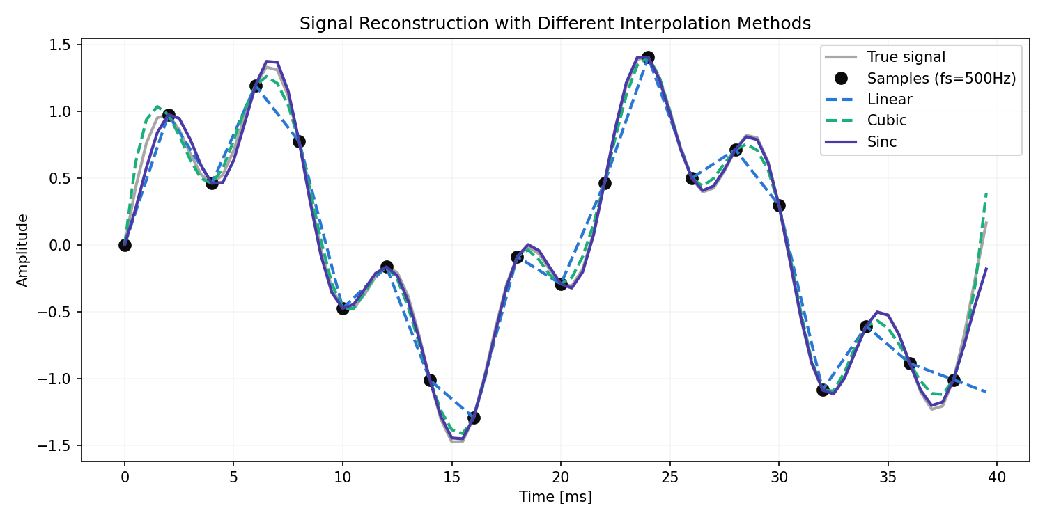
The plot shows Linear (blue dashed) approximating the signal with visible straight-line segments, while Cubic (green dashed) and Sinc (purple solid) nearly overlap the true signal (gray). Near the right edge (\(t > 38\) ms), Linear and Cubic both diverge quickly from the true signal due to extrapolation beyond the sample range — a visual confirmation of the extrapolation risk discussed above.
When the signal contains only frequencies below the Nyquist rate, sinc interpolation gives near-perfect reconstruction — but truncation produces edge errors. A common trick is to use sinc in the bulk of the signal and a smoother method (linear or spline) near the edges.
How Interpolation Error Depends on the Oversampling Ratio
The RMSE above was measured at a single sampling rate (500 Hz). Here we fix the observation window at 40 ms and vary the sampling rate \(f_s\) to see how each method’s RMSE changes. Define the oversampling ratio as
\[ r = f_s / 2f_{\max} \](with \(f_{\max}=180\) Hz).
import numpy as np
from scipy.interpolate import interp1d, CubicSpline


def sinc_interp(x_samples, t_samples, t_query):
    Ts = t_samples[1] - t_samples[0]
    T_grid, N_grid = np.meshgrid(t_query, t_samples, indexing="ij")
    sinc_matrix = np.sinc((T_grid - N_grid) / Ts)
    return sinc_matrix @ x_samples


T = 0.04
fs_high = 8000  # reference rate for a high-fidelity "true" signal
t_dense = np.arange(0, T, 1 / fs_high)
x_true = (np.sin(2 * np.pi * 50 * t_dense)
          + 0.5 * np.sin(2 * np.pi * 180 * t_dense))

fmax = 180.0
fs_list = np.array([380, 450, 500, 600, 700, 800, 1000, 1200, 1500, 2000, 3000])
results = {name: [] for name in ["Linear", "Cubic", "Spline", "Sinc"]}

for fs in fs_list:
    t_samples = np.arange(0, T, 1 / fs)
    x_samples = (np.sin(2 * np.pi * 50 * t_samples)
                 + 0.5 * np.sin(2 * np.pi * 180 * t_samples))

    linear = interp1d(t_samples, x_samples, kind="linear", fill_value="extrapolate")
    cubic = interp1d(t_samples, x_samples, kind="cubic", fill_value="extrapolate")
    spline = CubicSpline(t_samples, x_samples)
    x_sinc = sinc_interp(x_samples, t_samples, t_dense)

    for name, x_hat in zip(["Linear", "Cubic", "Spline", "Sinc"],
                           [linear(t_dense), cubic(t_dense), spline(t_dense), x_sinc]):
        rmse = np.sqrt(np.mean((x_true - x_hat) ** 2))
        results[name].append(rmse)

r = fs_list / (2 * fmax)
for name, vals in results.items():
    print(name, [f"{v:.5f}" for v in vals])
print("oversampling ratio r:", [f"{x:.2f}" for x in r])
Output:
Linear ['0.21605', '0.31903', '0.25184', '0.15235', '0.09654', '0.06678', '0.04028', '0.02856', '0.01899', '0.01093', '0.00483']
Cubic ['0.16042', '0.41156', '0.07786', '0.23704', '0.16533', '0.09354', '0.02657', '0.00736', '0.00086', '0.00030', '0.00009']
Spline ['0.16042', '0.41156', '0.07786', '0.23704', '0.16533', '0.09354', '0.02657', '0.00736', '0.00086', '0.00030', '0.00009']
Sinc ['0.06711', '0.07921', '0.06810', '0.05617', '0.04945', '0.04489', '0.03875', '0.03455', '0.03000', '0.02474', '0.01802']
oversampling ratio r: ['1.06', '1.25', '1.39', '1.67', '1.94', '2.22', '2.78', '3.33', '4.17', '5.56', '8.33']
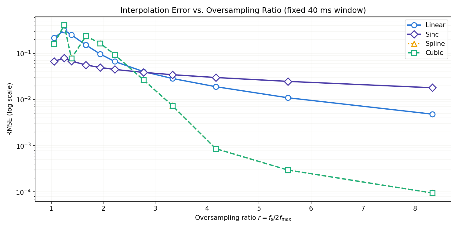
This result contradicts the naive intuition that “sinc is ideal, so it’s always best.” As the oversampling ratio \(r\) grows, Cubic/Spline’s RMSE drops faster than Sinc’s, and at \(r=8.33\) , Cubic/Spline’s RMSE (\(0.00009\) ) is two orders of magnitude smaller than Sinc’s (\(0.01802\) ). Let’s investigate why by looking at the spatial distribution of the error.
import numpy as np
from scipy.interpolate import interp1d


def sinc_interp(x_samples, t_samples, t_query):
    Ts = t_samples[1] - t_samples[0]
    T_grid, N_grid = np.meshgrid(t_query, t_samples, indexing="ij")
    sinc_matrix = np.sinc((T_grid - N_grid) / Ts)
    return sinc_matrix @ x_samples


T = 0.04
fs_high = 8000
t_dense = np.arange(0, T, 1 / fs_high)
x_true = (np.sin(2 * np.pi * 50 * t_dense)
          + 0.5 * np.sin(2 * np.pi * 180 * t_dense))

fs = 3000  # high oversampling ratio (r=8.33)
t_samples = np.arange(0, T, 1 / fs)
x_samples = (np.sin(2 * np.pi * 50 * t_samples)
             + 0.5 * np.sin(2 * np.pi * 180 * t_samples))

x_sinc = sinc_interp(x_samples, t_samples, t_dense)
x_cubic = interp1d(t_samples, x_samples, kind="cubic", fill_value="extrapolate")(t_dense)

err_sinc = np.abs(x_true - x_sinc)
err_cubic = np.abs(x_true - x_cubic)

n = len(t_dense)
lo, hi = int(n * 0.2), int(n * 0.8)  # central 60% of the window

print(f"Sinc  RMSE (full):     {np.sqrt(np.mean(err_sinc ** 2)):.5f}")
print(f"Sinc  RMSE (central 60%): {np.sqrt(np.mean(err_sinc[lo:hi] ** 2)):.5f}")
print(f"Cubic RMSE (full):     {np.sqrt(np.mean(err_cubic ** 2)):.5f}")
print(f"Cubic RMSE (central 60%): {np.sqrt(np.mean(err_cubic[lo:hi] ** 2)):.5f}")
print(f"Sinc  max error (edge 10%): {max(err_sinc[:n // 10].max(), err_sinc[-n // 10:].max()):.5f}")
Output:
Sinc  RMSE (full):     0.01802
Sinc  RMSE (central 60%): 0.00072
Cubic RMSE (full):     0.00009
Cubic RMSE (central 60%): 0.00001
Sinc  max error (edge 10%): 0.29210
Sinc’s error in the central 60% drops to \(0.00072\)
, not far from Cubic’s central error (\(0.00001\)
). But the full-window RMSE is \(0.01802\)
— 25 times the central value. The cause is that the maximum error in the edge 10% regions reaches \(0.29\)
. This is because our sinc_interp implementation truncates the sinc sum to samples strictly inside the 40 ms window: at the edges, the sinc’s tails are cut off, producing ringing errors via the same mechanism as the Gibbs phenomenon. Since the window length doesn’t shrink as \(f_s\)
increases, this truncation error does not shrink with higher \(f_s\)
. Cubic/Spline error, by contrast, is governed by how finely the local curvature between samples can be approximated, and it keeps shrinking as the sample spacing shrinks (higher \(f_s\)
). The practical lesson: in a fixed finite window, truncation error dominates sinc interpolation, and a theoretically “perfect” sinc reconstruction can lose to a local piecewise-polynomial method once enough samples are available.
Upsampling: scipy.signal.resample
scipy.signal.resample performs FFT-based zero padding in the frequency domain — essentially sinc interpolation.
from scipy.signal import resample, resample_poly

# Upsample by L = 4: 500 Hz → 2000 Hz
L = 4
x_upsampled_fft = resample(x_samples, len(x_samples) * L)

# resample_poly: polyphase FIR — much faster for long signals
x_upsampled_poly = resample_poly(x_samples, up=L, down=1)

print(f"Original:  {len(x_samples)} samples")
print(f"Upsampled: {len(x_upsampled_fft)} samples")
Output:
Original:  20 samples
Upsampled: 80 samples
resample is high quality but slow on long signals; resample_poly uses a polyphase implementation and stays fast. The internal polyphase machinery and detailed guidance on choosing between resample/resample_poly/decimate is covered with real benchmarks in
Multirate Signal Processing in Python
— see that article for the implementation depth. Here we focus on the principle: upsampling is equivalent to zero-stuffing plus an anti-imaging filter.
Downsampling: Preventing Aliasing
from scipy.signal import butter, sosfiltfilt, decimate

fs_orig = 1000
M = 4
fs_new = fs_orig // M
t = np.arange(0, 1, 1 / fs_orig)
x = np.sin(2 * np.pi * 50 * t) + 0.5 * np.sin(2 * np.pi * 300 * t)
# 300 Hz exceeds the new Nyquist (125 Hz) — aliasing must be prevented.

# --- Manual: anti-alias filter + decimate ---
sos = butter(8, fs_new / 2 - 5, fs=fs_orig, output="sos")
x_filtered = sosfiltfilt(sos, x)
x_decimated_manual = x_filtered[::M]

# --- scipy.signal.decimate (recommended) ---
x_decimated = decimate(x, M, ftype="iir")

print(f"Original:  {len(x)} samples at {fs_orig} Hz")
print(f"Decimated: {len(x_decimated)} samples at {fs_new} Hz")
Output:
Original:  1000 samples at 1000 Hz
Decimated: 250 samples at 250 Hz
decimate does both steps. ftype="iir" (default) uses an 8th-order Chebyshev I; ftype="fir" uses a 30-tap Hamming-window FIR. Pick IIR for speed, FIR for linear phase. The criteria for choosing between decimate and resample_poly, and tips for staging large decimation ratios across multiple passes, are covered in depth in
Multirate Signal Processing
.
Spectrum Comparison
To see how each method affects high frequencies, plot the spectrum of the interpolated signal. Linear interpolation leaves spectral images near integer multiples of \(f_s\) due to its \(\text{sinc}^2\) rolloff; spline and sinc suppress them effectively.
from scipy.fft import rfft, rfftfreq

methods = {"Linear": x_linear, "Cubic": x_cubic, "Sinc": x_sinc}
fig, ax = plt.subplots(figsize=(10, 4))
for name, x_hat in methods.items():
    X = np.abs(rfft(x_hat))
    f = rfftfreq(len(x_hat), 1 / fs_high)
    ax.semilogy(f, X / X.max(), label=name)
ax.set_xlabel("Frequency [Hz]")
ax.set_ylabel("|X(f)| (normalized)")
ax.set_title("Spectrum after Interpolation")
ax.set_xlim(0, fs_high / 2)
ax.legend()
ax.grid(True, alpha=0.3)
plt.tight_layout()
plt.show()
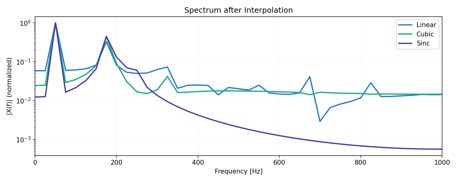
The plot shows Sinc (purple) decaying almost monotonically — and most sharply — above 200 Hz, while Linear (blue) retains visible peaks around 600–900 Hz. This visualizes the gentle \(\text{sinc}^2\) rolloff proven above (still only \(O(1/f^2)\) ) as high-frequency leakage. Cubic (green) sits between Linear and Sinc.
Recent Research
Classical interpolation theory (sinc, linear, polynomial, spline) assumes a regular time grid and a bandlimited signal. Recent research has begun relaxing this assumption.
Shabanov et al. (2024), “BANF: Band-limited Neural Fields for Levels of Detail Reconstruction” (CVPR 2024, project page ), tackles the fact that classical Fourier analysis and lowpass filtering don’t directly apply to neural fields (implicit neural representations) of 3D shapes and scenes. A simple architectural change makes the field itself decomposable into frequency bands, enabling level-of-detail representations and sampling on regular grids (e.g. for marching cubes). This extends the “bandlimiting as convolution with a kernel” idea behind sinc and linear interpolation into a world without an explicit signal representation.
Also, as noted above, Pakiyarajah, Pavez, & Ortega (2024), “Irregularity-Aware Bandlimited Approximation for Graph Signal Interpolation” (ICASSP 2024), proposes a bandlimited approximation for graph signal processing that accounts for irregular node placement — one direction for extending the uniform-grid interpolation theory covered here to arbitrary graph structures and non-uniform layouts.
Summary
- Ideal signal reconstruction is sinc interpolation (Whittaker–Shannon), and its interpolation property — \(\text{sinc}(k)=\delta[k]\) — provably reproduces the sample values exactly.
- Linear interpolation uses a triangular kernel (the self-convolution of two rectangular pulses); its spectrum’s \(\text{sinc}^2\) shape follows rigorously from the convolution theorem.
- Cubic interpolation’s standard parameter \(a=-0.5\) follows from the requirement of exactly reproducing quadratics, confirmed numerically down to floating-point precision.
- Measured RMSE at \(f_s=500\) Hz: Linear \(0.2283\) > Cubic \(\approx\) Spline \(0.0634\) > Sinc \(0.0607\) — matching the theoretical ordering.
- But in a fixed-length window, sinc interpolation’s error is dominated by truncation (Gibbs-like) and plateaus, while local methods (Cubic/Spline) keep improving as the oversampling ratio rises — a two-order-of-magnitude gap at \(r=8.33\) . “Sinc is always best” is not always true.
- Runge’s phenomenon, Gibbs-like ringing, extrapolation, non-uniform sampling, and pre-existing aliasing are pitfalls easily overlooked when choosing an interpolation method.
- Upsampling = zero-stuff + anti-imaging filter. Downsampling = anti-alias filter + decimate. Order matters.
The key insight is that interpolation is filtering — every interpolator can be viewed as convolution with a kernel having a specific frequency response.
Related Articles
- Sampling Theorem — the Nyquist condition, aliasing, and the perfect-reconstruction proof this article builds on. This article picks up the “recovery” side as a comparison of interpolation kernels.
- Z-Transform and Digital Filter Design — pole-zero analysis of interpolation filters.
- Fast Fourier Transform (FFT) with Python — the FFT used to evaluate interpolation spectra.
- Window Functions and Power Spectral Density — windowing for finite-length sinc truncation.
- FIR vs IIR Filters — choosing anti-alias / anti-imaging filters.
- Moving Average Filters Compared — moving average as a simple lowpass.
- DTFT, DFT, and FFT: Putting the Hierarchy in Order — Interprets the spectrum after upsampling-interpolation through the DTFT/DFT/FFT hierarchy.
- Discrete Cosine Transform (DCT) — DCT basis functions used in image interpolation and compression; a useful comparison point for resampling.
- Autocorrelation Function and Power Spectral Density — Background for evaluating periodicity and PSD after interpolation.
- Filter Design: Comprehensive Guide — Design guidance for anti-imaging filters used in upsampling.
- Time-Frequency Analysis Guide — Understand how resampling affects time-frequency representations.
- DSP x ML Roadmap — Where interpolation / resampling fit in the DSP-to-ML pipeline.
- Discrete DSP Fundamentals Roadmap — A hub linking sampling, interpolation, DFT, Z-transform, autocorrelation, and DCT. Interpolation is the implementation-side pillar of the reconstruction guaranteed by the sampling theorem.
- Multirate Signal Processing in Python: Decimation, Interpolation, and Polyphase Filters
— Extends the interpolation-kernel comparison here to decimation, rational L/M rate conversion, and efficient polyphase implementations. The
resample/resample_poly/decimateimplementation details and benchmarks live there.
References
- Keys, R. G. (1981). “Cubic Convolution Interpolation for Digital Image Processing.” IEEE Trans. Acoustics, Speech, and Signal Processing, 29(6), 1153-1160.
- Oppenheim, A. V., & Schafer, R. W. (2009). Discrete-Time Signal Processing (3rd ed.). Prentice Hall.
- Smith, J. O. (2002). Digital Audio Resampling Home Page. CCRMA, Stanford University.
- Shabanov, A., Govindarajan, S., Reading, C., Goli, L., Rebain, D., Yi, K. M., & Tagliasacchi, A. (2024). “BANF: Band-limited Neural Fields for Levels of Detail Reconstruction.” CVPR 2024, 20571-20580. Project page
- Pakiyarajah, D., Pavez, E., & Ortega, A. (2024). “Irregularity-Aware Bandlimited Approximation for Graph Signal Interpolation.” ICASSP 2024. arXiv:2312.09405
- SciPy Interpolation
- SciPy Signal Resampling